How focal position and feedrate are essential for high quality cutting with a fiber laser-cutting
By Joe Fiorito, Applications Engineer at Mazak Optonics Corp.
Due to their small beam size and high wattage capabilities, fiber laser systems excel at cutting with nitrogen. As with all laser cutting, this requires the correct combination of settings in order to get the cleanest cut possible. This is especially important if you want to take advantage of the cutting speeds that fiber lasers can achieve.
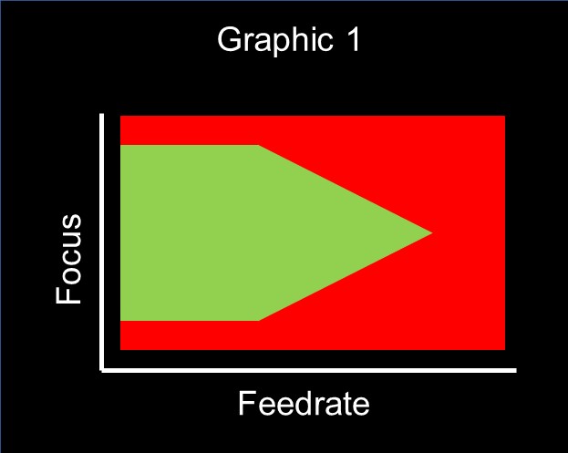 The most important cutting parameters are going to be your focal position and your feedrate. For any given material there will be an optimum focal position where you can achieve your best cut quality and fastest cut speeds. To the right, you can see Graphic 1 represents this. The green area is parts that cut well, and the red area is parts that don’t cut well or not at all. As you can see the faster you cut, the range of viable focus values gets smaller.
This same concept can be applied to other cutting parameters as well like gas pressure, power, duty cycle, etc. However, they might not exhibit this pattern in the same exact way.
With the understanding of these patterns, we can utilize this knowledge in order to develop cutting conditions. If you are unsure of which parameters you should change in order to dial in your cut, the first thing to adjust is always going to be your focal position.
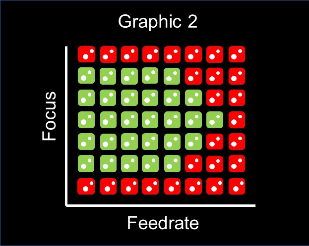 We can break down Graphic 1 into individual blocks that represent different focus values. If we look at Graphic 2, we can see a range of focus values that returns a good quality cut. This range of good focus values is usually around +/- 0.020” from your ideal focus value.
The first step is going to move your focus upward or downward in increments of 0.020” until you can see the cut get noticeably worse. From that point, return to your original focus value and do the same in the other direction until it gets noticeably worse again. The halfway point between these two focus values is going to be your ideal focus.
Now that we have our optimum focal position, we can move on to the remaining parameters. The next field to adjust is going to be gas pressure. We can utilize the same technique we used earlier here. However, instead of adjusting our focus in increments of 0.020”, we will be adjusting our gas pressure by around 5-10% at a time. Once this is completed, we can then move on to our feedrate. Adjustments for feedrate should be about 2-5%.
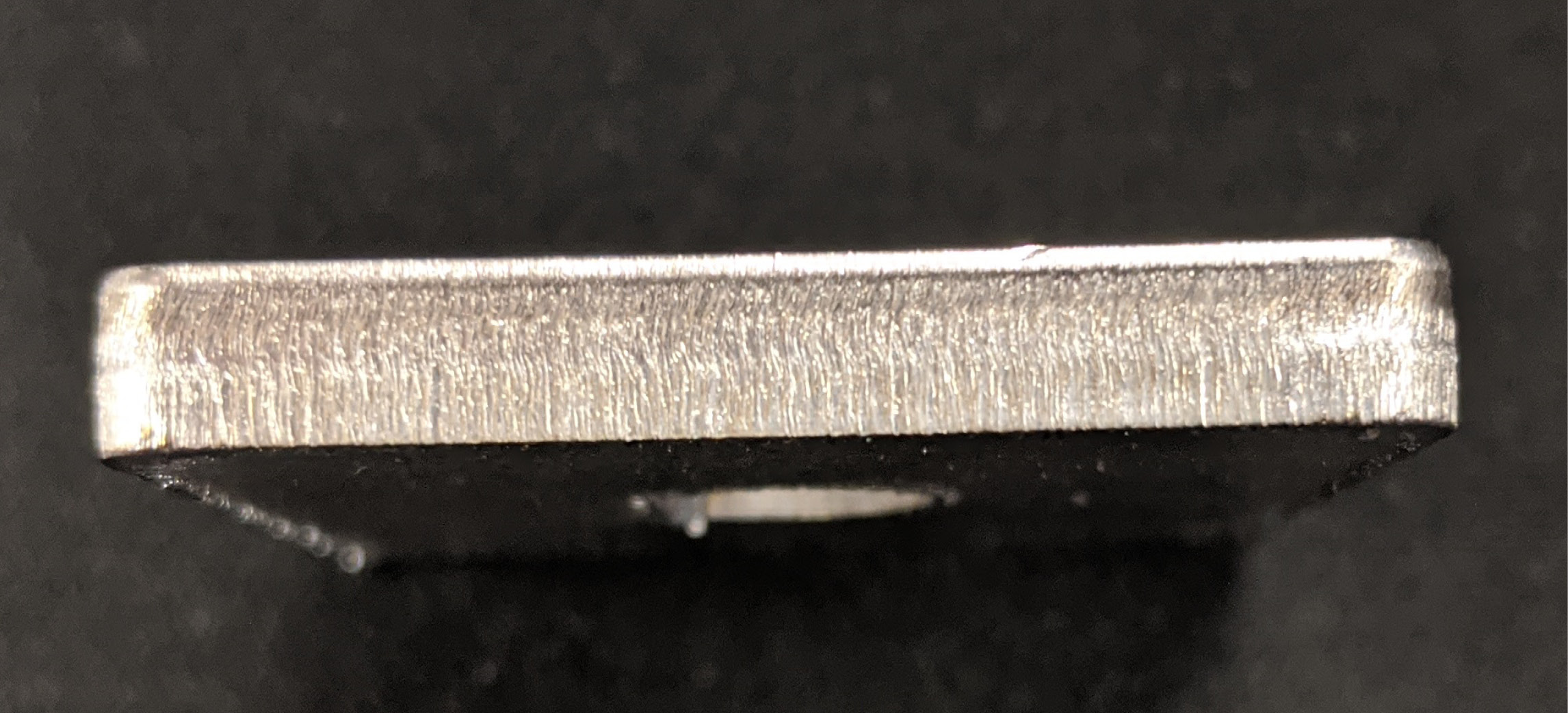
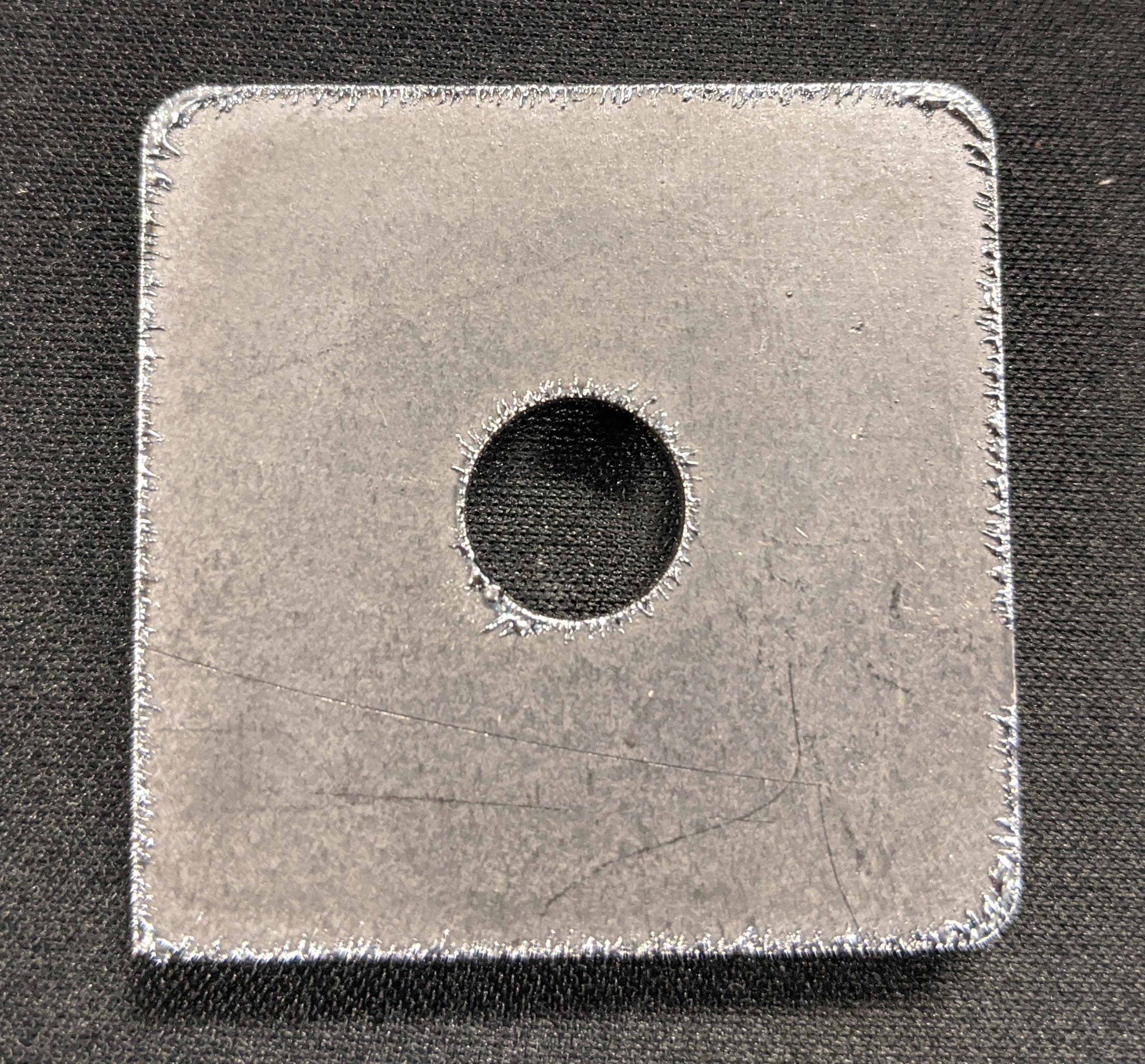
That said, there are characteristics you can see in the edges of the cuts which can give you hints as to which parameters need to be adjusted. A simple, overarching rule of thumb is that if you see dross that is purely hanging underneath the edge of the material then that is an indication of the focal position being too low and/or gas pressure being too high. On the contrary, if you see imperfections that start before the bottom edge of the material this can mean the focal position is too high and/or the gas pressure is too low. Below are some examples of several nitrogen cuts that were cut on an OPTIPLEX NEXUS FIBER 6kW.
*All of these examples were cut with a negative focal position. In some instances, towards the maximum machine capacity, your condition may flip to a positive focus and some of these suggestions may not apply. *
| Photos | Problem | Possible Causes |
|---|---|---|
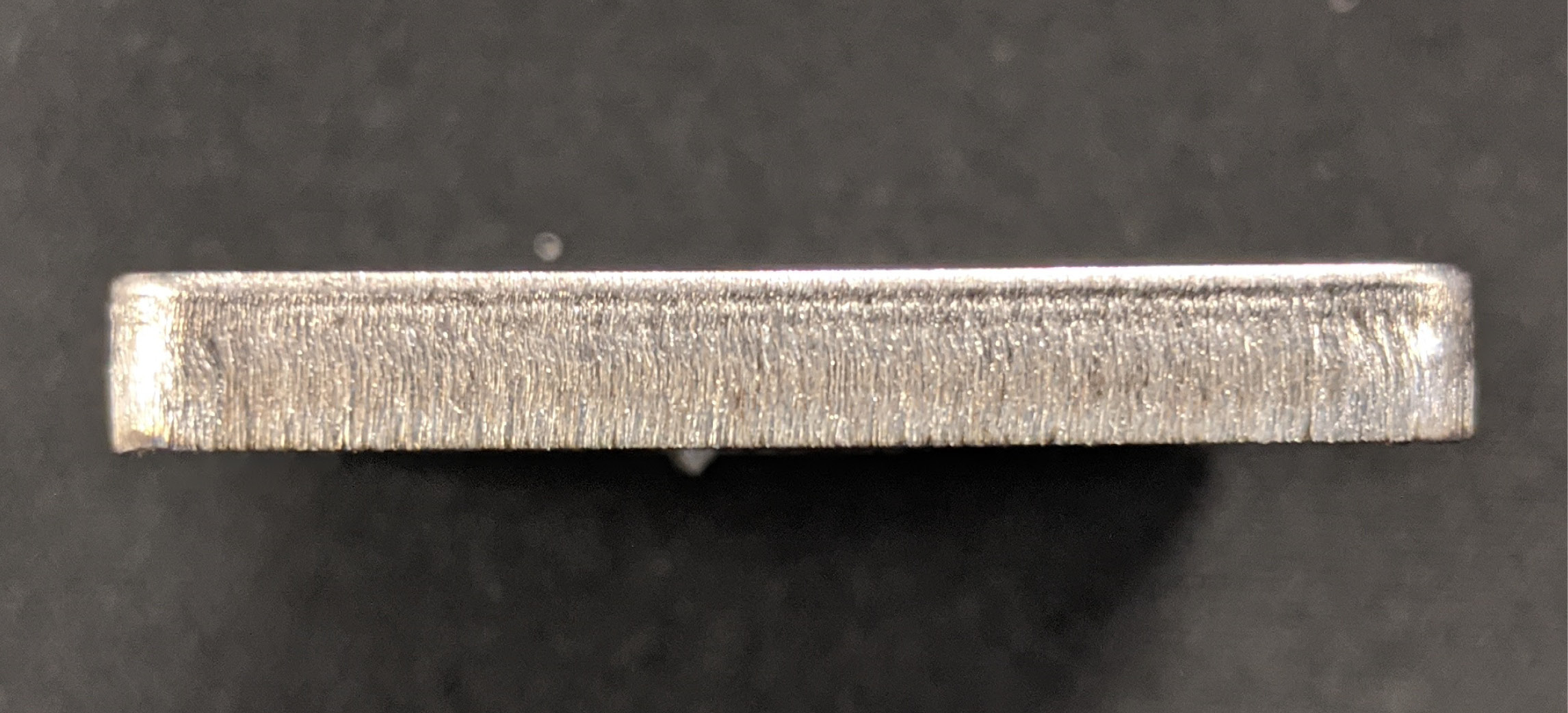 |
No issue Smooth cuts Potentially small black |
Good cutting tech |
|
|
Dross hanging or "Globs" of material |
Focus too low Gas pressure too high Gap too low Feedrate too high |
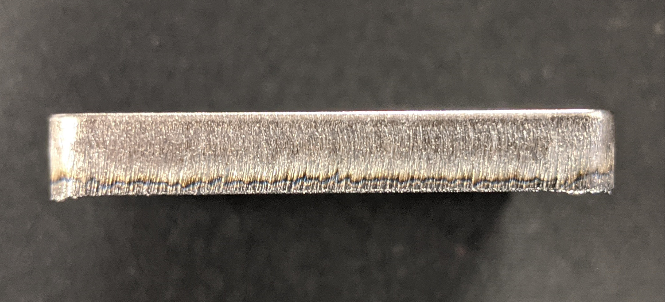 |
Large black marks/line on the side of the material which leads to dross underneath |
Focus too high Gas pressure too low Gap too high |
| Photos | Problem |
Possible Causes |
|---|---|---|
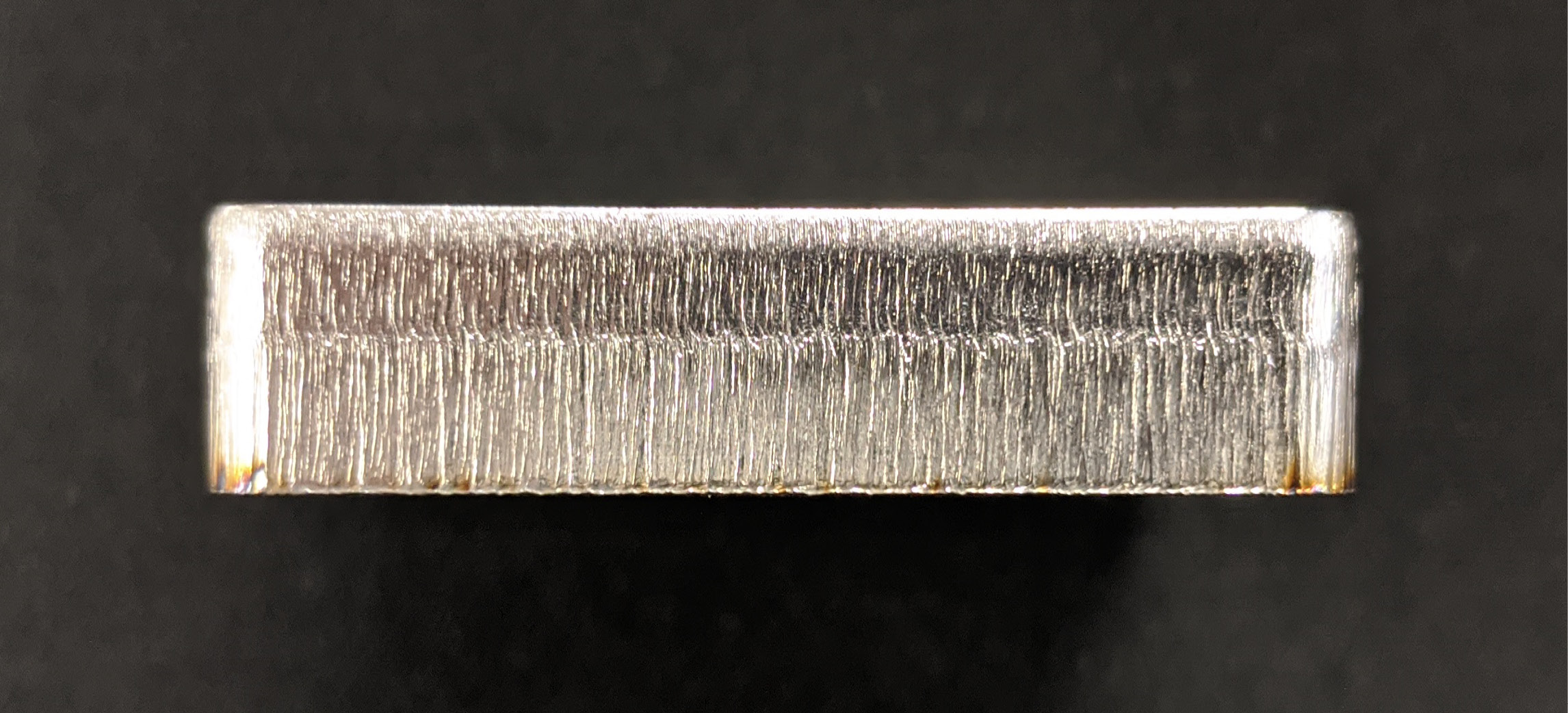 |
No issue Smooth cuts |
Good cutting tech |
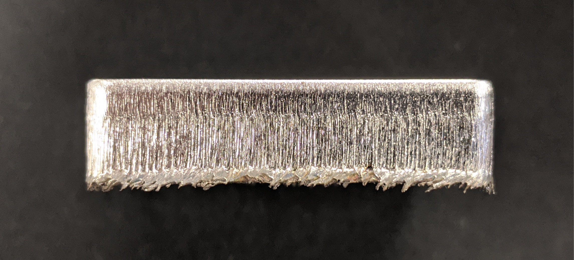 |
Grey-ish dross of black/ discolored gouges in edge of material |
Focus too high Gas pressure too low Gap too high |
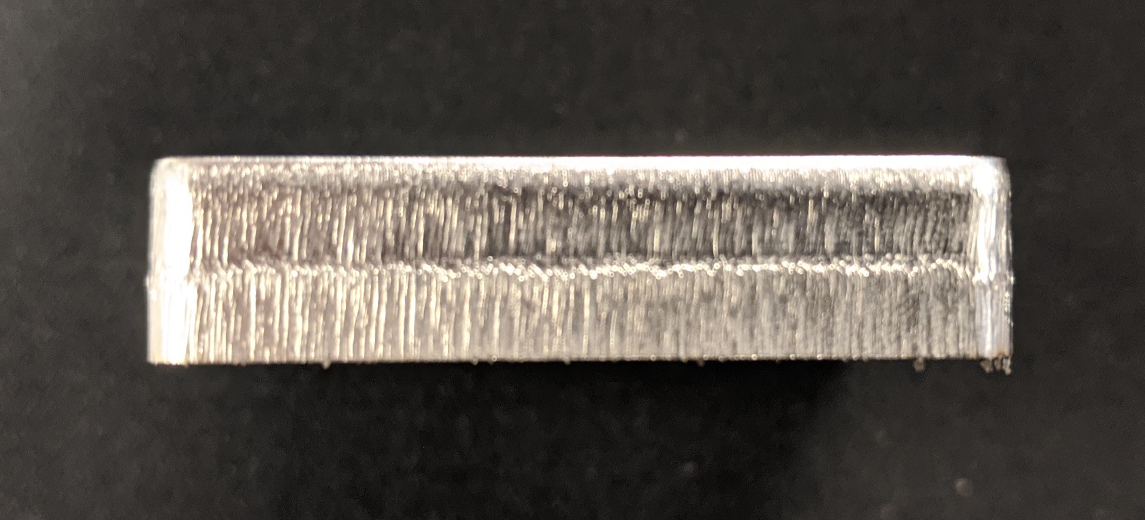 |
Plasma Irregular striations Bright green glow while |
Focus too low Gas pressure too high Cutting too fast |
| Photos | Problem | Possible Cause |
|---|---|---|
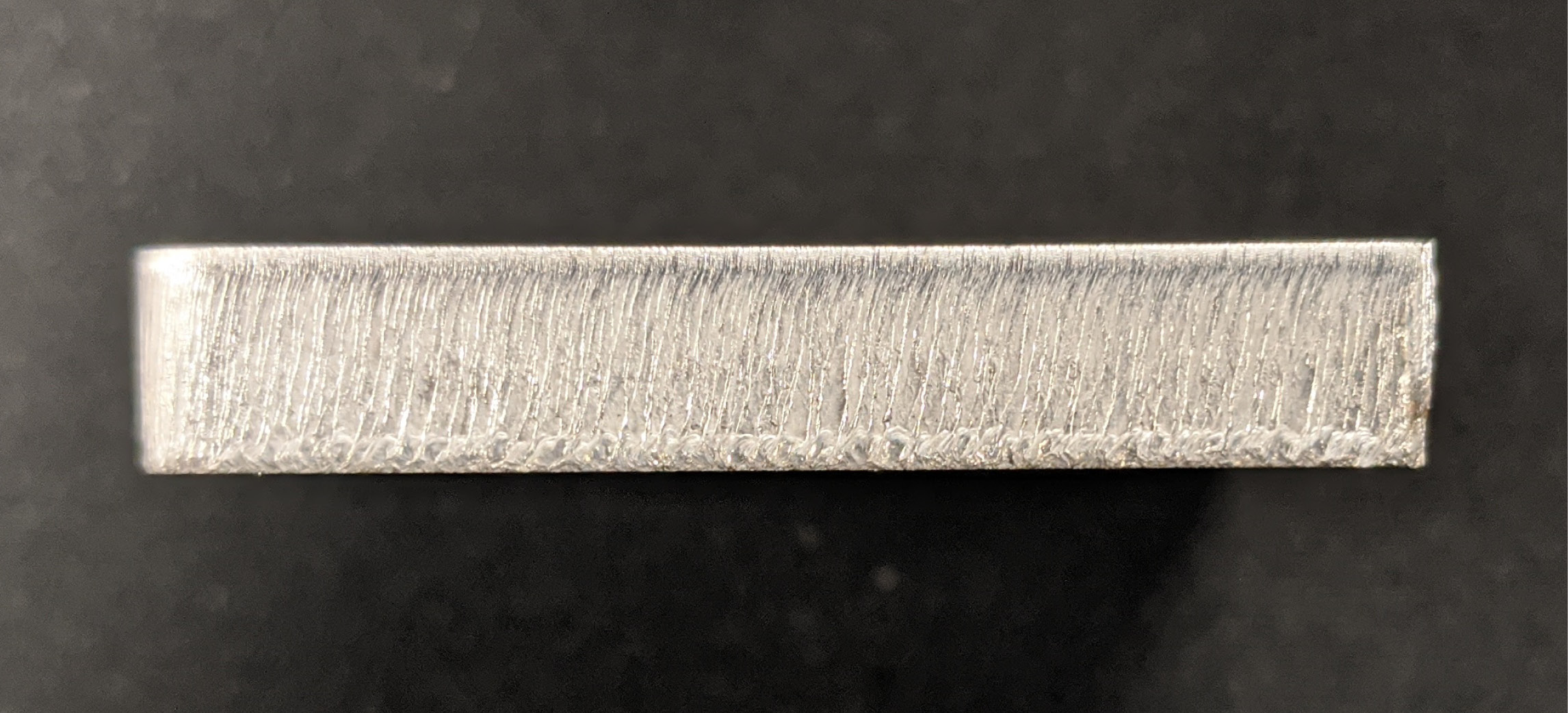 |
No issue Smooth cuts Potentially small bead |
Good cutting tech |
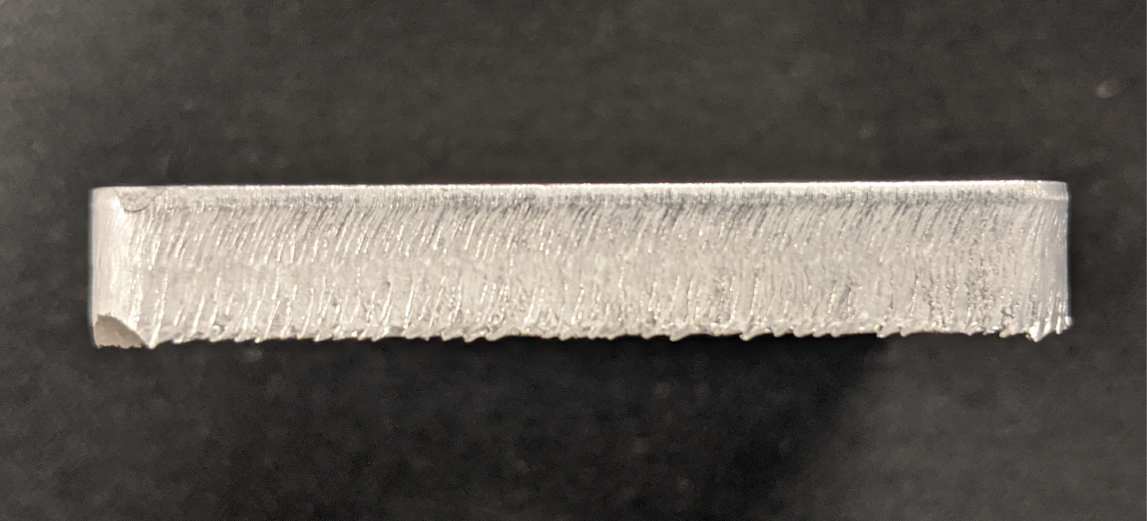 |
Hard, pointy dross hanging underneath the edge of the material |
Focus too low Gas pressure too high Gap too low |
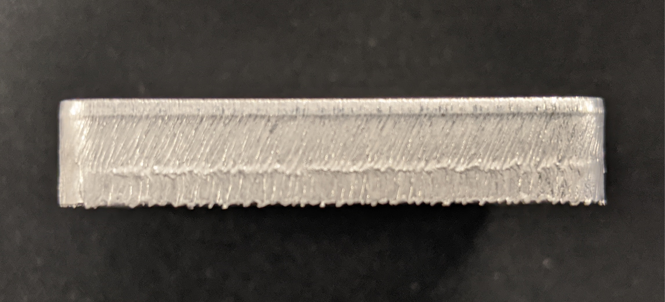 |
Plasma Irregular striations Dross on part Bright green glow |
Focus too low Gas pressure too high Gap too low Feedrate too fast |
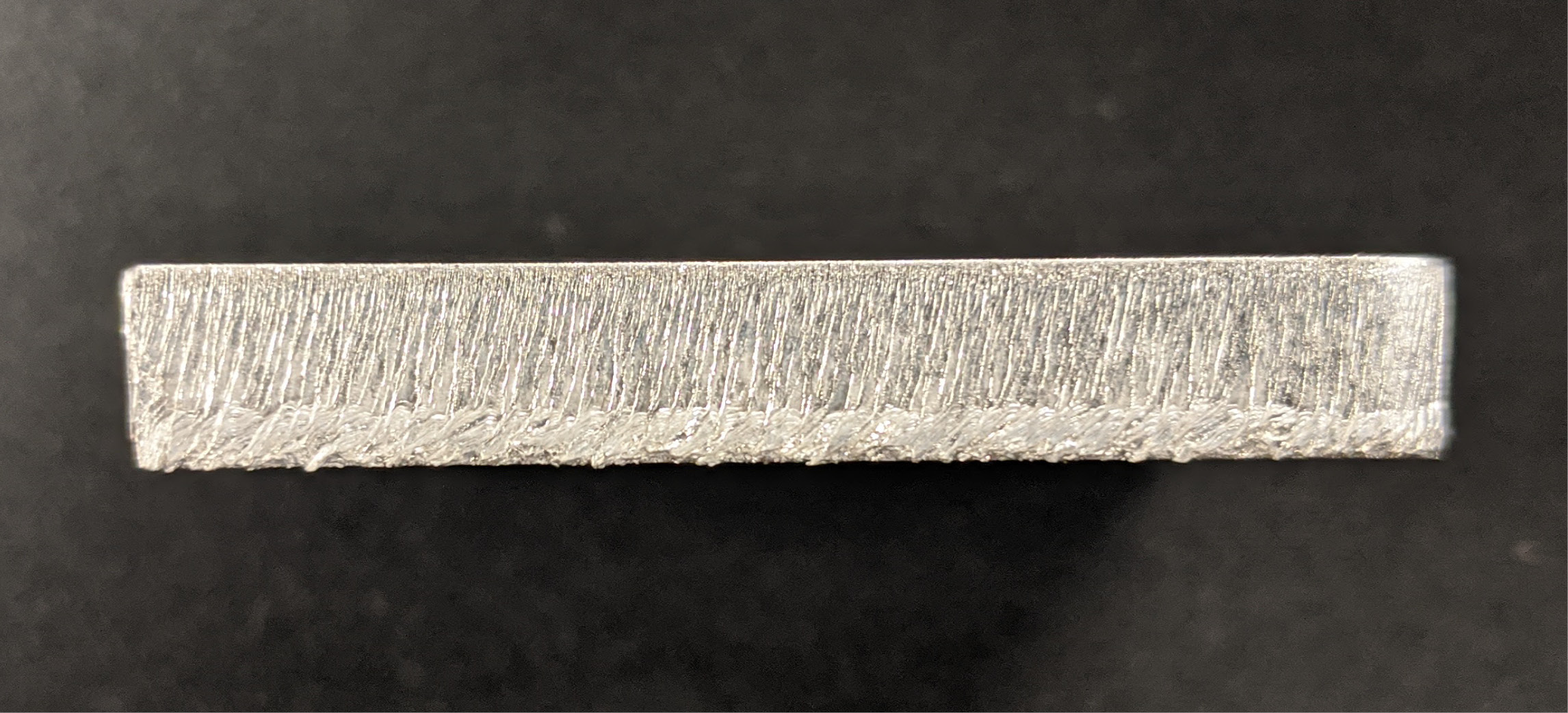 |
Buildup on edge of |
Focus too high Gas pressure too low Gap too high |
For additional assistance, please contact the Mazak Software Department at 1-888-MAZAK-US.
