
Reduce processing times while still maintaining cut quality and accuracy.
by Joe Fiorito, Applications Engineer at Mazak Optonics Corp.
Flash Cutting is a technique that can be used to process particular patterns more efficiently. Any time there is a pattern where the straight lines of different features line up, Flash Cutting can be used. Flash Cutting results in greatly reduced processing times while still maintaining cut quality and accuracy.
Instead of cutting each feature (square, hexagon, etc.) individually, it is more efficient to process all the lines in one particular orientation in succession by 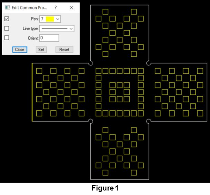 quickly turning the beam on and off. For example, in Figure 1, Flash Cutting will cut the horizontal lines of the squares in one pass and the vertical lines in the next pass. This process can then be repeated until all features are cut. For squares, rectangles, and diamonds this will require 2 passes total; for hexagons, it will require 3 passes.
In order to Flash Cut parts in Mazak Smart System, all that is needed is to change the pen color of the features that should be Flash Cut. Flash Cutting is going to be denoted by Pen 7 which is a yellow color.
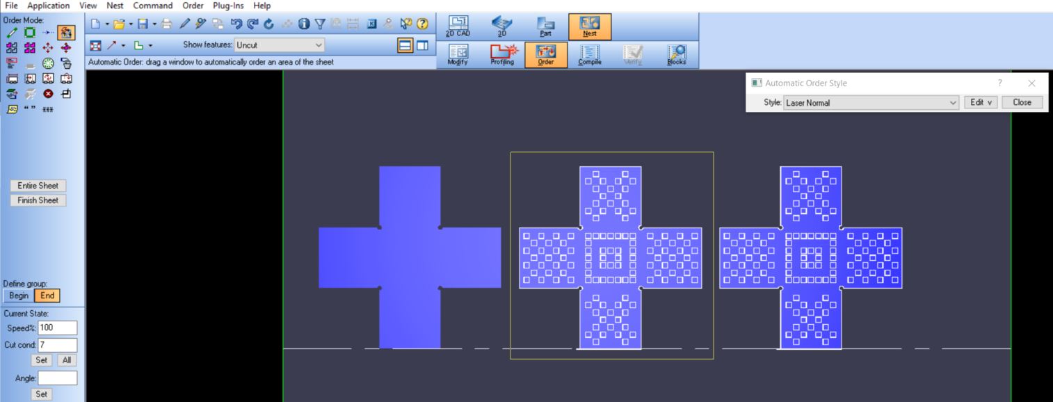
Once Flash Cut features are set, programmers can move forward with the rest of the programming process as normal. Once arriving at ORDER mode, the “Laser Normal” order text will apply the Flash Cutting. By default, the Mazak Smart System software is going to first perform all the Flash Cutting for the entire sheet. Depending on the nest, this may be inefficient if Flash Cut parts are far apart. If it is ideal to Flash Cut part by part, simply select part by part in ORDER mode by drawing a box around each part in the preferred processing order.
After that, compile code as normal and send it out to the laser. The Flash Cutting is going to be called out by a G86 code, so look for those codes in the program to verify everything is set up properly.
Once the laser operator is out at the machine, there are a few things that need to be set up in order to successfully Flash Cut.
First, operators will need to set up a Condition 7. This is going to be the Flash Cutting condition. To make things easier, copy Condition 1 over to line 7 to get a good starting point. From here, a few modifications are needed to cleanly and safely Flash Cut parts.
As a general rule of thumb, the OPTIPLEX NEXUS FIBER platform can Flash Cut about 500 IPM, while the OPTIPLEX FIBER platform can Flash Cut about 1000 IPM—provided that these do not exceed the regular Condition 1 feedrate. These numbers will change based on the acceleration and deceleration distance in the code. For more information on this, please contact the Mazak applications department.
The next adjustment required includes raising the cutting height to reduce the chances of spatter hitting the protective window. A Gap setting of 0.5mm is typically enough.
When raising the cutting height, it is also important to lower the focus and increase the gas pressure in order to maintain good cut quality. The amount to raise the Gap is going to determine how much to lower the focus. Since the Gap is measured in mm and the focus is in inches, use the conversion of 1mm ≅ 0.040 inches. If the gap is raised from 0.0mm to 0.5mm, then lower the focus by 0.02 inches. With this raise in gap, it is necessary to increase the gas pressure by 10-20%.
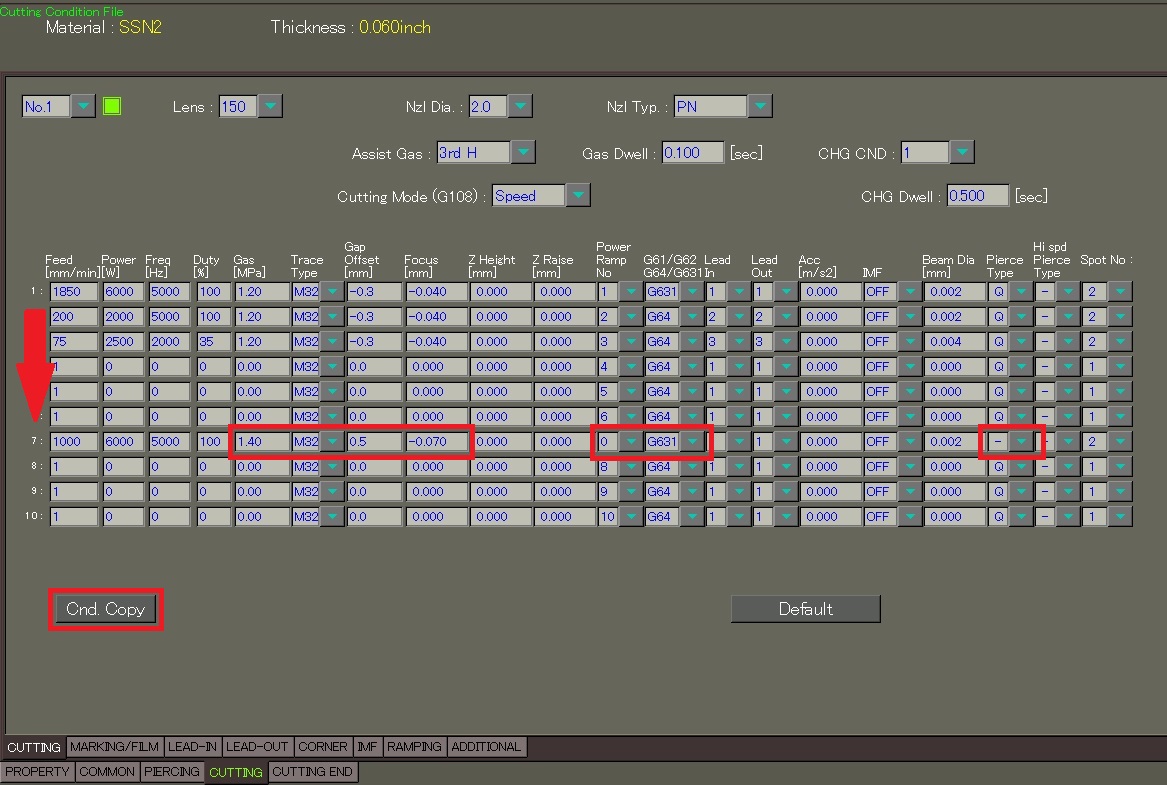
Now, the last adjustments needed are to set Power Ramp No to 0 as no power ramping is needed, also make sure that Corner deceleration code is set to G631 to use optimum machine acceleration, and finally that Pierce Type is set to “-” as no pierces are needed.
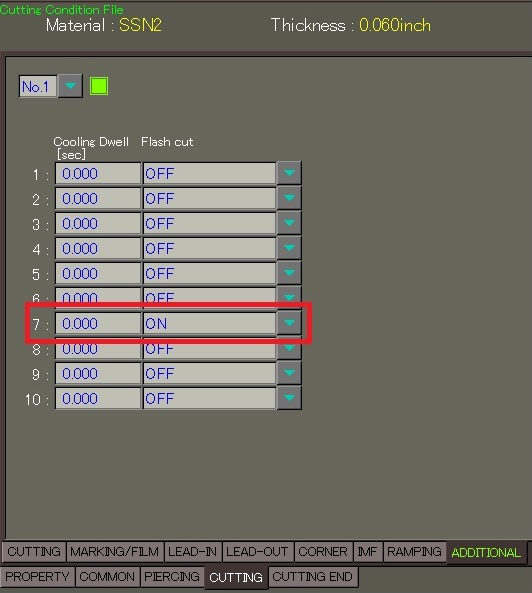
Following that, the final step is to enable Flash Cutting on the CUTTING > ADDITIONAL tab.
With the programs set up in Mazak Smart System and cutting conditions set at the machine, it is time to start Flash Cutting and increasing laser-cutting efficiency.
For additional assistance, please contact the Mazak Applications Department at 1-888-MAZAK-US.