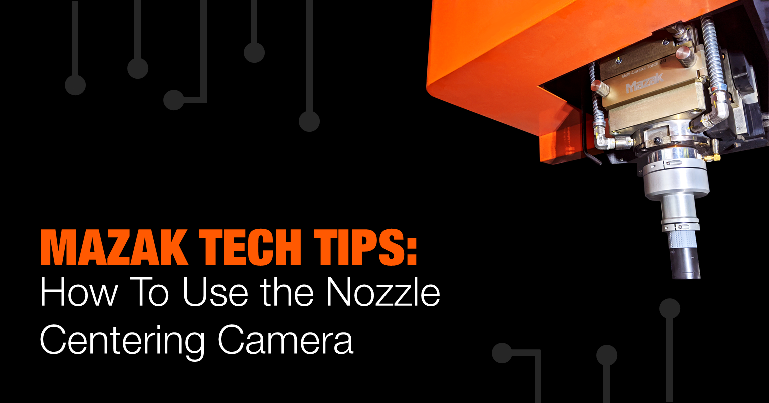
Reduce setup time and eliminate tape shots when utilizing the nozzle centering camera.
by Tim Tapper, Applications Manager at Mazak Optonics Corp.

Since the introduction of laser-cutting machines in the 80’s, the advancements in technology, machine capabilities, and available options have been increasing by leaps and bounds. Modern machines cut better, faster, and require less operator intervention than ever before. One task that has remained unchanged over the years is the need to manually center the beam within the nozzle tip.
The process of nozzle centering has taken many forms over the years, but most people are familiar with shooting a hole in a piece of tape to tell if the beam is passing through the center of the nozzle tip. This was accomplished by placing tape on the end of the nozzle and firing the beam to make a small hole in the tape. Using a magnifying glass, the operator would then inspect the hole in the tape to see if it was in the center of the nozzle orifice. This was referred to as a “Tape Shot”.
The tape shot method was slow and was left up to operator interpretation. The results could vary from one operator to the next. Properly performing this procedure often impacted the cut quality of the finished parts. This method is still used by many laser manufacturers to this day.
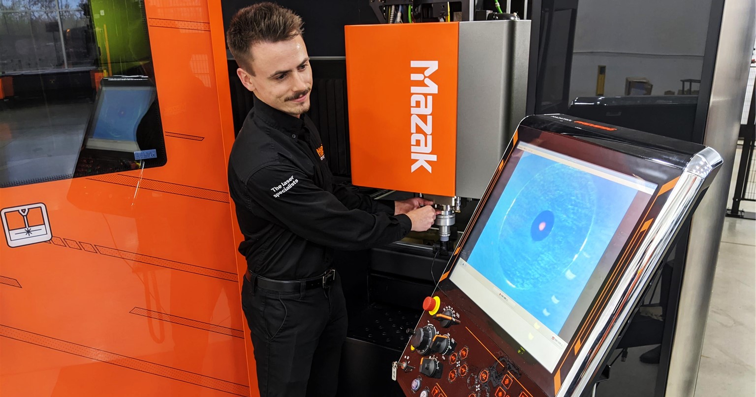
Recently, Mazak has introduced an innovative option for vastly improving the speed and consistency of the nozzle centering process using a special camera. The camera can be installed over the nozzle tip on the cutting head to allow for a real time magnified view of the bottom of the nozzle. The image is shown on the machine control and allows the operator to see the position of a red alignment laser as it exits the nozzle tip.
The operator can visually see the movement of the alignment laser inside the nozzle opening as adjustments are made. It is obvious when the beam is centered and only takes seconds to complete the process. This has reduced downtime and improved the cutting consistency of the machine by ensuring the centering process is always perfect.
This option is available for any fiber machine with a Preview III control or newer. The step by step process of using the camera is described below.

- Run G22U0S3 with MDI Mode
- Open SWITCH screen. ( MAINTENANCE > SWITCH )
- Press AXIS STROKE2 SELECT
- Move X & Y axis close the control
- Connect the camera to the USB port on the controller
- Attach the camera under the torch
- Click the icon for the camera application on the control
- Turn on the Alignment Laser
- Adjust the nozzle centering as needed
For additional assistance, please contact the Mazak Applications Department at 1-888-MAZAK-US.
