Strategies to implement in order to successfully cut mild steel plate
by Tim Tapper, Applications Manager at Mazak Optonics Corp.
Successfully processing thicker mild steel plate (3/16” and thicker) with oxygen on fiber lasers can be challenging at times due to variations in plate composition, rust and scales issues, and difficulties managing heat buildup in the plate. Fortunately, Mazak laser-cutting machine tools come stocked full of options for combating the challenges associated with thick mild steel cutting. Knowing which techniques to apply and when can be a little intimidating, especially for new laser users. Following these different strategies will shed some light onto the mysteries surrounding mild steel plate cutting.
Plate Composition and Quality
Material composition can greatly impact the cutting quality and required cutting parameters when processing thicker mild steel with oxygen. The differences in chemical composition will change the melting point of the steel. Since the laser is essentially a heat source, as the melting point changes, so does the cutting conditions.
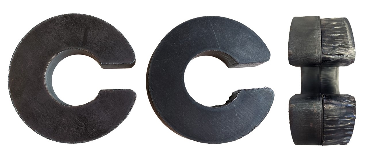
Below is an example of two different grades of steel (left A36, right grade 50). In this case you can visually see the difference in surface color. Both materials were processed with the exact same cutting conditions. In one case these conditions produced a high quality cut, but on the other material these conditions produced a less than ideal cut. Different material grades will require their own separate cutting conditions.
Factors which can affect the cut quality are:
- Material composition
- Surface rust
- Surface scale
If you are running high quality material and still having cutting issues, follow the following tactics to improve .
Verify Machine Setup
If you are having difficulties cutting thicker mild steel with oxygen, before making changes to your standard cutting conditions, first make sure the machine is in good working order and the machine is setup correctly per the cutting conditions manual. Be sure to check the following items to confirm:
- Check the condition of the protection window
- Check the nozzle tip for damage or debris
- Check the nozzle centering
- Perform nozzle calibration
- Verify the cutting conditions match the manual
Inspect the Lower Torch Assembly for Damage
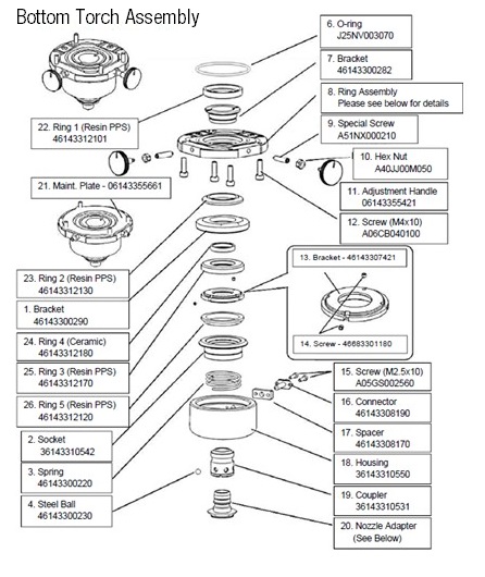
If everything listed above is fine, please refer to training documents and Section 9 of the machine maintenance manual to inspect the lower torch. Follow these steps:
- Disassemble the bottom torch assembly
- Look for burnt or damaged components
- Cleanup any dust or debris
- Replace damaged components
- Reassemble the bottom of the torch
- Repeat nozzle centering and calibration
Verify the Nozzle Cooling Functionality
The next item to check, since is ensuring proper operation of the nozzle cooling system. This is essential since thick mild steel cutting often requires a small diameter nozzle tip (1.0mm – 1.5mm) and low oxygen assist gas flow through the nozzle.
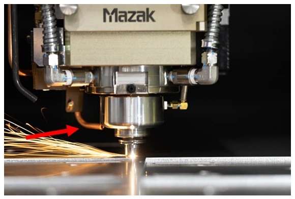
Confirm that the copper nozzle cooling line is pointed directly toward the nozzle coupler, as shown here. Contact with tipped up parts can cause misalignment of this tube reducing the effectiveness of the nozzle cooling air flow. If the copper nozzle is bent, you can easily bend it back into place.
Verify the Nozzle Cooling J-Parameters
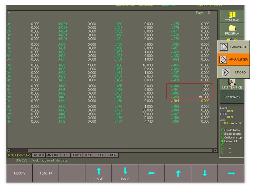
There are four parameters which control the nozzle cooling function. These parameters can enable/disable the function and control the range of materials where nozzle cooling is active. Make sure J490 – J493 match the following:
- Press the PARAMETER menu button
- Press the MPARAMETER sub menu button
- Press the PAGE DOWN menu button until J490 – J494 is visible
- Verify the J-Parameters as follows:
- J490 = 1.0
- J491 = 1.0
- J492 = 1.0
- J493 = 50.0
If modifications are required:
- Highlight the corresponding J-parameter
- Press the MODIFY menu button
- Enter the new J-parameter value
- Press CONFIRM to change the value.
- Repeat for additional modifications
Setup Automatic Nozzle Cleaning Function
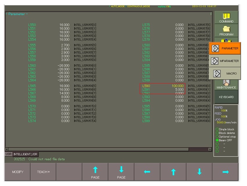
If you are having complications completing your nest with consistency, you can have the machine automatically clean and calibrate the nozzle tip after processing a predetermined number of features. This ensures that any debris building up on the nozzle over time is removed automatically before affecting cutting performance. The target number of processed features before cleaning will vary depending on material thickness and application.
- Determine target number of features for cleaning function (ex: 100)
- Press the PARAMETER menu button
- Press the PARAMETER sub menu button
- Select the INTELLIGENT_USER tab for L-parameters
- Highlight parameter L590
- Press the MODIFY menu button
- Enter the target number in L590
- Press CONFIRM to change the value
- Change L591 to 5.0 if needed
Verify Oxygen Assist Gas Flow
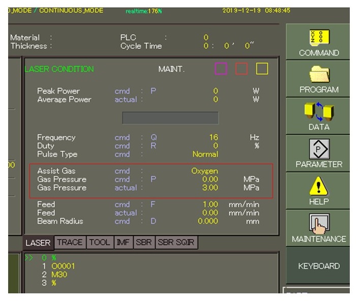
Maintaining proper oxygen assist gas flow is crucial when processing thick mild steel. In the COMMAND screen you can compare the commanded assist pressure to the actual assist gas pressure coming out of the nozzle tip. There should be no more than a +/- 10 percent variance in these values when running the machine in production.
If the variance exceeds this value:
- Verify oxygen flow from source
- Verify pressure on tank regulator (150 psi)
- Call Mazak Service for assistance
Check for Assist Gas Leaks
The machine can cut with oxygen, nitrogen, and compressed air. Some of the assist gas lines in the machine are common to all three of the assist gas types. For this reason, it is possible for one gas to potentially leak into the other during processing.
Oxygen purity is important when processing thick mild steel on a laser-cutting machine. A small amount of nitrogen or air leaking into the oxygen lines on the machine can produce poor cutting results. To verify that there is not an assist gas leak internal to the laser machine, use the following guidelines:
- Turn off the N2 and/or air assist gas to the machine
- Bleed out the N2 and air pressure to the cutting head
- Retry cutting the thick mild steel with oxygen with all other gasses turned off
If the cutting is better with the other gasses turn off to the machine, call Mazak Service for assistance in troubleshooting the assist gas leak.
Programming Suggestions
Implementing certain programming techniques from your CAD/CAM software can influence the consistency and cut quality when processing thicker mild steel with oxygen. Utilizing the correct techniques can be the difference between success and failure. Try these techniques to improve consistency.
- Add cooling dwells at the end of leadins and sharp corners
- Add corner radii to sharp corners (10% of material thickness or more)
- Use “Double Cut Leadins” to start the cut after the pierce
- Stagger part sequencing to avoid heat buildup in the sheet
For detailed information on adding proper programming techniques, contact Mazak software support.
Piercing Consistency
Without a good, clean pierce when processing thicker mild steel with oxygen, chances are the cut will not start out properly, even if the cutting conditions are perfectly fine tuned. Adjusting the EIA pierce sub program for thicker mild steel is quite simple. It involves one value in the pierce sub program for that material. Use the following guidelines for pierce adjustments:
- Open the Tech-Table file for the current material
- Select the EIA Pierce tab of the Tech-Table
- Open the EIA Pierce sub by pressing EDIT
- ½” Mild Steel sub program shown on right
- Modify #470 to adjust the pierce aggressiveness
- Increase the value to add extra pierce time
- Decrease the value to speed up the pierce
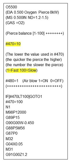
Note: Slower pierces will be less aggressive and less likely to blow out during the piercing process.
For additional assistance, please contact the Mazak Optonincs applications department at: 1-888-MAZAK US.
