

Achieve high accuracy and optimal efficiency when cutting sharp corners, holes and other small features.
by Joe Fiorito, Applications Engineer at Mazak Optonics Corp.
While lasers are known for high speed and high accuracy cutting, they spend a fair amount of time cutting at less than top speed. Sharp corners, holes, and other features require the laser to slow down to process. There are two machine functions we can control in order to process these features efficiently and accurately, the cutting head and power.
Controlling the Cutting Head
On one side of things we can control the physical behavior of the cutting head. This is controlled though the corner deceleration codes. These codes can be found in the CUTTING screen then CUTTING tab and there is a selection for each cutting condition. The options (in order of most often used) for these codes are G631, G64, G61, G62.
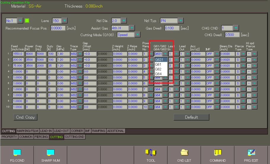
G631 - High Speed, High Accuracy Mode
The most preferred option is G631 - High Speed, High Accuracy Mode. While in this cutting mode, the laser will look ahead at the next block and calculate exactly how quickly it can process that feature. This will utilize the maximum machine acceleration possible for each feature, so this is going to result in the fastest processing while still making accurate parts. This is the preferred setting for most high-speed cutting applications.
G64 - Continuous Cutting Mode
The simplest of these options is G64 - Continuous Cutting Mode. While in this cutting mode, the laser will maintain the commanded cutting feedrate through all the cut features. This may lead to rounded corners and inaccurate parts. However, these issues can be alleviated with proper use of G09 (exact-stop) codes. That said, this is the preferable cutting mode when you are cutting thick mild steel with oxygen.
G61 - Exact-Stop Check Mode
The next cutting mode is G61 - Exact-Stop Check Mode. While cutting in this mode the laser will perform an exact-stop at the end of each block. This will ensure sharp corners and accurate parts. However, this is also going to cause exact-stops when they are not always required. For example, the laser will stop two times on a radiused corner: once when it enters the corner, and again when it is leaving the corner.
G62 - Automatic Deceleration Mode
The last option is G62 - Automatic Deceleration Mode. While in this cutting mode, the laser will drop to a pre-determined acceleration to cut small features. But the laser will also start decelerating earlier than it would while in other cutting modes. Since the laser drops to a particular acceleration limit, the laser will sacrifice a small bit of accuracy for faster cutting speeds. The laser will end up cutting very small radii at all sharp corners as well.
Controlling Power
When it comes to processing corners and small features, controlling the movement of the cutting head is only one half of the story. As the laser slows down to cut these smaller features, using the same amount of power when cutting full command speed is not recommended. It is necessary to reduce the power by using Power Ramping. Controlling how the laser reduces power is found in the CUTTING screen then RAMPING tab. The options (in order of most often used) for ramping are G283, G181, G182 and G81.
G283 - Fine Power Ramping
The most preferred option for power ramping modes is G283 - Fine Power Ramping. The feedrate in G283 is a threshold feedrate which controls when the laser will start reducing its power. Once the laser drops beneath that feedrate, it will drop to the power, frequency, and duty cycle set on the ramping screen. This allows operators to achieve more control of the cut quality while the laser is ramping the power down. For example, when cutting a 90-degree corner laser operators can set the G283 feedrate larger in order to start ramping further away from the corner. Conversely, the smaller the feedrate is then the closer the laser will get to the corner before reducing the power.
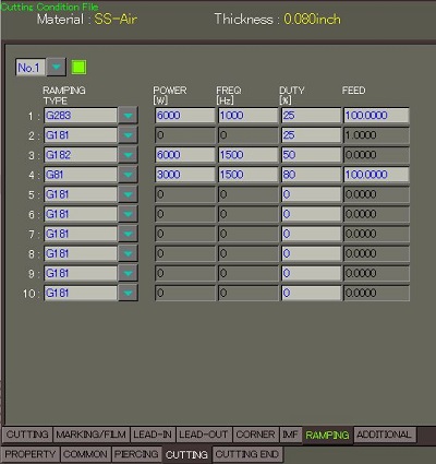
G181 - Real-Time Power Ramping
The next type of ramping we have is G181 - Real-time Power Ramping. When this ramping mode is enabled the laser will dynamically reduce and increase the power as the laser slows down and speeds up as it processes all the features in the program. The only parameter operators control while using G181 is the duty cycle. This ends up being is the minimum duty cycle the laser can drop down to while it ramps down. One thing to keep in mind while using G181 is that the laser is going to be pulsing at the frequency designated in the main cutting condition while it reduces the duty cycle. It may be necessary to fine tune the heat, which can be done by adjusting the frequency on the CUTTING screen to CUTTING tab.
G182 - Extended Real-Time Power Ramping
An additional ramping option available is G182 - Extended Real-Time Power Ramping. This option functions similar to G181, the laser will dynamically adjust the heat going into the cut as it slows down and speeds up. However, now operators can control the power and frequency in addition to the duty cycle.
G81 - Power Ramping
The last type of ramping control is G81 - Power Ramping. When this is enabled, an operator can set a reduced speed cutting condition that the laser will drop to when it slows down. Operators can set the power, frequency, duty cycle, and the cutting feed rate. This setting is not used much because it is not very versatile.
Ramping Issues and Causes Chart
Dialing in these ramping setting can get difficult if operators do not know what to look for. In some instances, not having enough power in the corners looks quite similar to having too much power. Each material has its own subtle tell as whether it is too hot or too cold. Below are some examples of MSN2, ALN2, and SSN2.
| Photos | Problem | Possible Causes |
|---|---|---|
 |
Corner quality matches rest of part |
Corner ramping settings |
|
|
Beads of dross and scorch marks at corners |
Too much heat in corners |
 |
Dross underneath part, plasma before and after corner |
Not enough power in ramping settings |

| Photos | Problem | Possible Causes |
|---|---|---|
 |
Corner quality matches rest of part |
Correct ramping settings |
 |
Dross starting before bottom edge of part |
Too much heat in corners |
 |
Small, beady dross Losing cut in corners |
Not enough power in ramping settings |
| Photos | Problem | Possible Cause |
|---|---|---|
 |
Corner quality matches rest of part |
Correct ramping settings |
 |
Beads of dross at corners |
Too much heat in corners |
 |
Small, beady dross entering and existing corners |
Not enough power in ramping settings |
For additional assistance, please contact the Mazak Applications Department at 1-888-MAZAK-US.