
Maximize your laser-cutting production and minimize loss by utilizing these five Mazak Smart System software programming tools and techniques
By Michael Sharpe, Software Engineer
Are you taking full advantage of your laser cutting machine? Having fully integrated software is essential in order to maximize your laser-cutting machine’s full capabilities. If the machine can do it and it is programmable, the software must be able to support these capabilities.
In today’s highly technological world, software has become increasingly more powerful. These advances allow fabricators to cut more efficiently while also saving time in programming which all together results in higher profitability. Check out these five major techniques and tools that you can use with Mazak Smart System to make your laser-cutting processes most efficient.
Batch nesting
Back in the day, when software capability posed limitations, the traditional style of nesting was to have every part enclosed in an imaginary rectangle, which was nested by the software. Unfortunately, this form of nesting does not allow you to truly optimize sheet utilization.
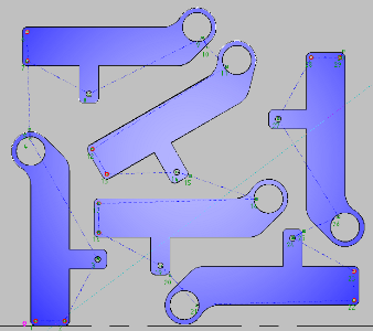
The next revolution of nesting was shaped parts nesting. This is where the software could look at the actual part geometry, and arrange them on the sheet, to make the most of the material available. Shaped part nesting allows nests to fit more parts on a sheet by arranging them more closely together. This nesting strategy has been the accepted “norm” for many years now.
The most recent transition, which started roughly a year ago, is to use intelligent nesting technique across multiple nests, not just one. This process involves arranging the first nest then looking for ways to improve it. Once it is optimized, the software moves to the second nest, comparing it to the first nest to see if there are parts that could be nested more efficiently by looking at both nests in their entirety. This process continues through the rest of the nests and, in most circumstances, the software is able to achieve more efficient nests by looking at them as a complete project rather than a collection of individual nests.
Efficient cutting
Batch nesting can handle individual parts and common line cut parts. Common line cutting is a style of nesting. This can be achieved through associating attributes to a part file. These include: material type, material thickness, assist gas to be used, angular or rotation control and common line cutting. Parts can be flagged for common line cutting and then nested as groups or freeform.
Common line cutting is when a cut path is shared by two or more parts. This process eliminates piercing, improves material utilization and reduces overall cutting time. But, common line cutting can only be done with parts that lend themselves to this process.
Smart order
Reducing downtime is a major component to increasing throughput. A common issue that results in downtime is a collision. A collision occurs when the torch bumps into a cut part that has tipped up. These are called tip ups, which are processed parts that do not lay flat on the machine’s slats and are now protruding higher than the flat sheet. Good software provides tools to avoid tip ups.
 The first and most traditional way to eliminate tip ups is through tabbing your nest. Tabbing is where you program the parts to not be completely cut, by having it still slightly connected to the skeleton of the material. Tabbing parts ensures that cut parts lay flat on the sheet and do not move around or tip up. This is especially important when processing thin sheet material, the parts sometimes see-saw on a slat and are more likely to tip up. Using automatic tabbing applies a tab to the lead-in position to stabilize the part while eliminating additional piercing.
But now there is a better way to do avoid tip ups. The newest way to combat tip ups is to allow the Mazak Smart System to find an intelligent order when processing the sheet through a process called smart order. This technique eliminates the need to program tabs. The intelligent smart order process defines the cutting order so that the torch never crosses over a previously processed part or cutout, thereby eliminating collision risk. In conjunction with smart order is smart order lead-in. This is where the lead-ins are positioned automatically to occur where you exit the cut. Again, this ensures that the torch does not cross over the processed parts and eliminates the risk of a collision.
Eliminating the possibility of a collision is crucial to reducing machine downtime. Smart order and smart order lead-in are the answer to that risk.
Full speed cutting parameters
CNC machinery has improved by leaps and bounds since their creation. The machine’s control intelligence has advanced so much so that it now can simplify the work for software programmers.
Traditionally with programming, if there was a small hole a different pen would be selected in order to define the cutting speed which would hold the tolerance. But now, the machines can preview what parts are ahead and the machine knows to adjust cutting parameters without the program needing to define it.
Programs can now be created with no need to define cutting parameters. Mazak laser-cutting machines will then automatically define the maximum speed allowed to cut each part geometry. This allows the programmer to delegate the necessary cutting speed to the machine instead of manually inputting it into the program. This process can greatly impact the cutting process by maximizing efficiency and maintaining accuracy.
Scrap efficiencies
Of course it is important to intelligently program parts, but it is also vital to program efficient ways to cut scrap material. Utilizing slug destruct as well as sheet skeleton destruct, minimizes downtime during manual parts removal process. By having the slugs and skeleton set up this way, it simplifies the scrap removal process. Scrap cutting also helps with stress relief in the material itself.
Another component of scrap is offcutting and remnant tracking. An offcut is performed when a portion of the material is not utilized for parts. The offcut function cuts the material to have a straight edge allowing the remnant material to be used another time, which leads to remnant tracking. The Mazak Smart System software can store the remnant material information, and reintroduce the offcut the next time a nest uses that material. The software also allows you to snap to a preferred off cut size which then standardizes all your remnant sizes.
By having these unused remnant pieces available for another nest, it reduces scrap and increases material utilization which equals money saved in the laser-cutting process.
All together now
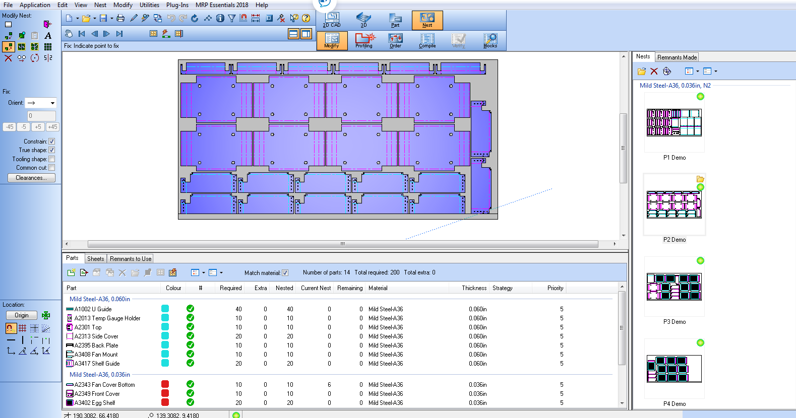
All of these steps can be easily accomplished through the Mazak Smart System single interface project manager dashboard. Instead of having multiple menus, this dashboard allows you to have all of these tools in one location, making it quick and accessible while also being interactive.
The project manager dashboard is divided into three sections. The top part is the graphic nest. It shows the full sheet with all the parts laid out on it. You can work on these nests in this section. The bottom part of the dashboard shows the schedule which can be shown as pictures of the parts or as the name of the parts. It is customizable to your preference. This section shows which parts are still needed to be added into a nest. Once a nest is completed through the nester, the right side panel shows completed nests and remnants made.
The project manager also allows you generate reports of the nests, materials necessary and sheets needed. The project manager dashboard is the ideal format for performing, monitoring and completing the nesting process.
These are just a few 2D software tips and tricks to make your laser-cutting machine and overall operations more efficient and productive.