Mazak's technology continues to change the world
Technology & Solutions
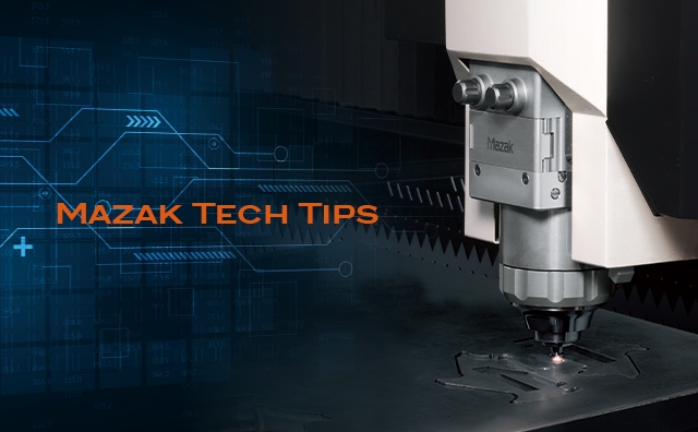
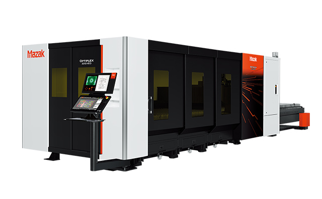
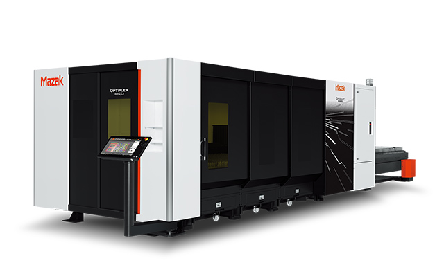
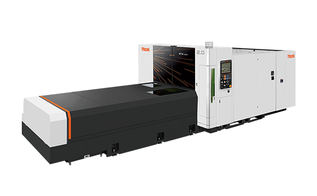
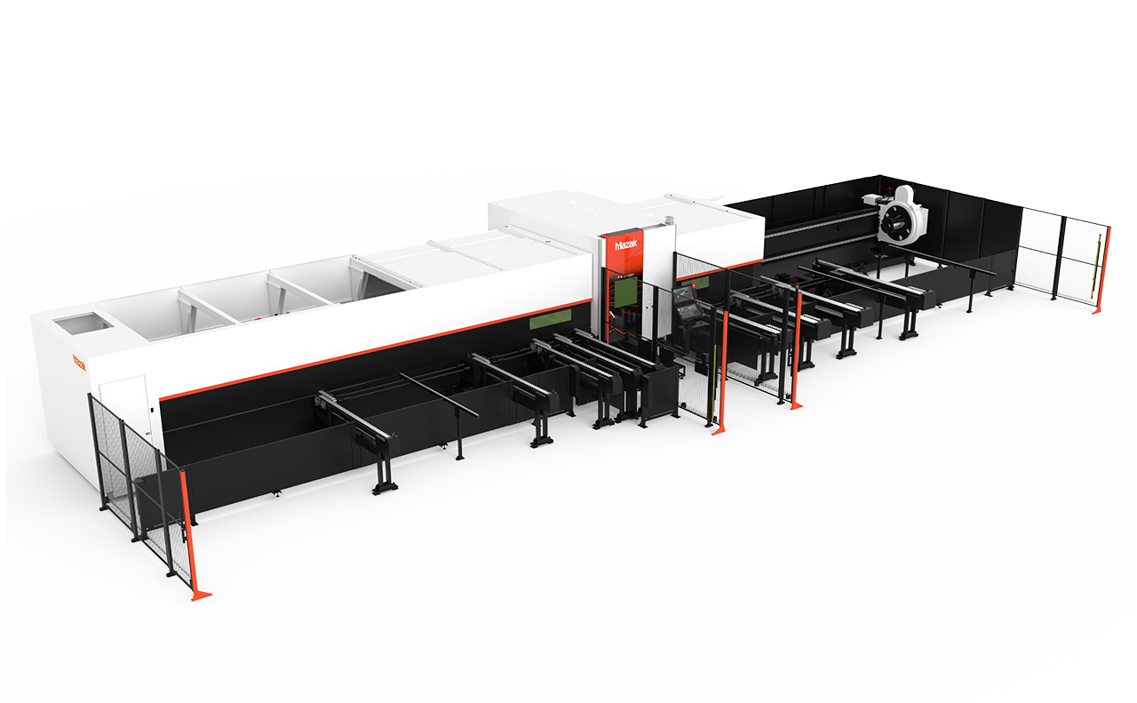
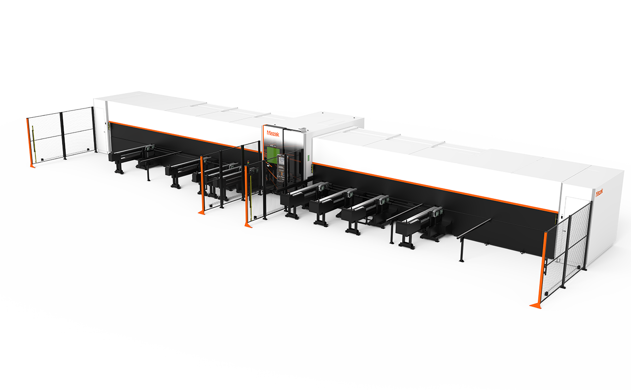
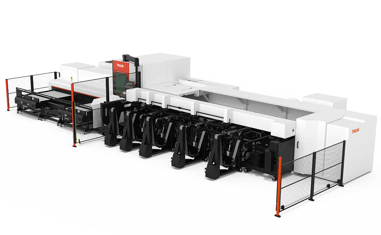
Innovation in production activities with laser processing machines. This is supported by Mazak's state-of-the-art technology. Mazak's laser processing machines continues to evolve by multiple technologie. Mazak provides products and solutions that can support a wide range of parts machining processes, such as high-speed and high-accuracy machines, various automation systems, and production support software and CNC equipment that support skill leveling and setup.